

Hammer mills: hammermills
In the feed processing process there may be a number of ingredients that require some form of processing. These feed ingredients include coarse cereal grains, corn which require particle size reduction which will improve the performance of the ingredient and increase the nutritive value. There are a many ways to achieve this particle size reduction, here we are looking at using hammer-mills, for information on roller mills, see the related links at the bottom of this page.
Both hammering and rolling can achieve the desired result of achieving adequately ground ingredients, but other factors also need to be looked at before choosing the suitable method to grind. Excessive size reduction can lead to wasted electrical energy, unnecessary wear on mechanical equipment and possible digestive problems in livestock and poultry. For more in depth information regarding what actually occurs to the ingredients during size reduction please refer to this link: particle size reduction.
- are able to produce a wide range of particle sizes
- work with any friable material and fibre
- ease of use
- lower initial investment when compared with a roller
mill
- minimal maintenance needed
- particles produced using a hammermill will generally
be spherical, with a surface that appears polished.
Disadvantages:
- less energy efficient when compared to a roller mill
- may generate heat (source of energy loss)
- produce greater particle size variability (less uniform)
- hammer mills are noisy and can generate dust pollution
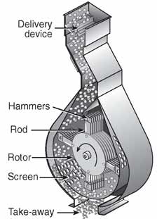
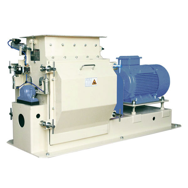
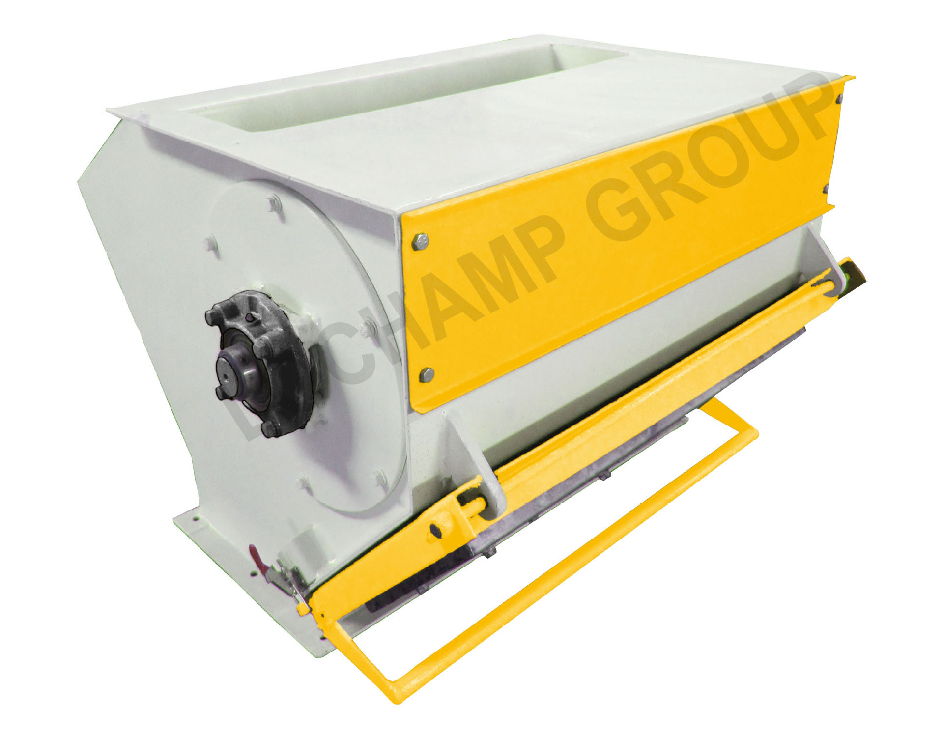
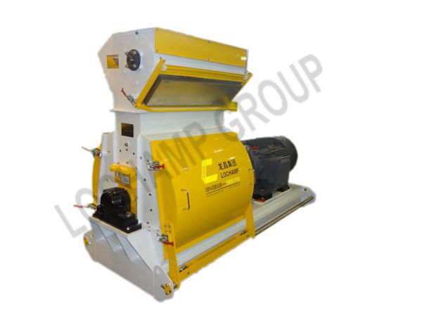
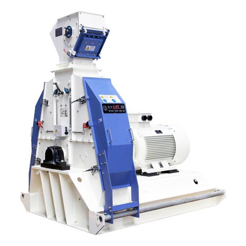
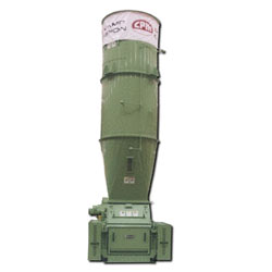
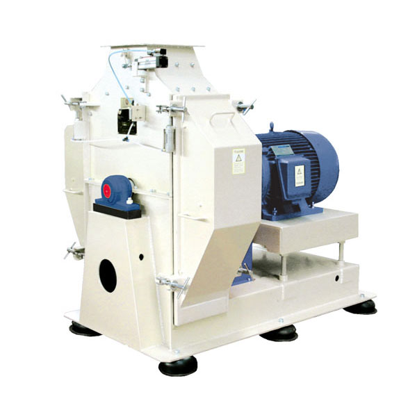
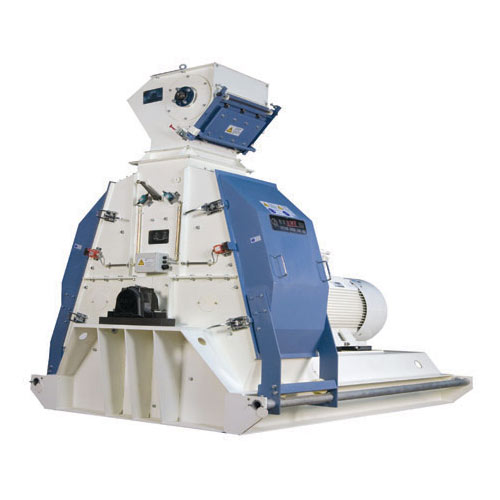
General Design
The major components of these hammermills, shown in the picture, include:
- a delivery device is used to introduce the material to be ground into the path of the hammers. A rotor comprised of a series of machined disks mounted on the horizontal shaft performs this task.
- free-swinging hammers that are suspended from rods running parallel to the shaft and through the rotor disks. The hammers carry out the function of smashing the ingredients in order to reduce their particle size.
- a perforated screen and either gravity- or air-assisted removal of ground product. Acts to screen the particle size of the hammer mill to ensure particles meet a specified maximum mesh size.
Feeder design
Materials are introduced into the paths of the hammers by a variable speed vein feeder. This type of feeder can have its motor slaved by a programmable controller to the main drive motor of the hammer mill. The operational speed of the feeder is controlled to maintain optimum amperage loading of the main motor.
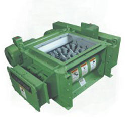
Hammer design and configuration
The design and placement of hammers is determined by operating parameters such as rotor speed, motor horsepower, and open area in the screen. Optimal hammer design and placement will provide maximum contact with the feed ingredient.
Hammer mills in which the rotor speed is approximately 1,800 rpm, should be using hammers which are around 25cm (~ 10 inches) long, 6.35cm (~2.5 inches) wide, and 6.4mm (0.25 inches) thick. For a rotor speed of about 3,600 rpm, hammers should be 15 to 20 cm (~ 6-8 inches long, 5 cm (~ 2 inches) wide, and 6.4 mm (0.25 inches) thick.
The number of hammers used for a hammer mill of 1,800 rpm, should be 1 for every 2.5 to 3.5 horsepower, and for 3,600 rpm, one for every 1 to 2 horsepower. Hammers should be balanced and arranged on the rods so that they do not trail one another. The distance between hammer and screen should be 12 to 14 mm (~ 1/2 inch) for size reduction of cereal grains.
The velocity or tip speed of the hammers is critical for proper size reduction. Tip speed is the speed of the hammer at it's tip or edge furthest away from the rotor, and is calculated by multiplying the rotational speed of the drive source (shaft rpm) by the circumference of the hammer tip arc. See the following formula:
A common range of tip speeds seen in hammermills is commonly in the range between 5,000 and 7,000 m/min (~ 16,000 and 23,000 feet per minute). When the tip speeds exceed 23,000 feet per minute, careful consideration must be given to the design of the hammer mill, the materials used in its construction, and the fabrication of all the components. Simply changing the rotational speed of the drive source is not a recommended method of increasing hammer speed in excess of 23,000 feet per minute.
Impact is the primary force used in a hammermill. Anything which increases the chance of a collision between a hammer and a target; increases the magnitude of the collision; or improves material take-away provides an advantage in particle size reduction. The magnitude of the collisions can be escalated by increasing the speed of the hammers.
Screen Design
The amount of open area in a hammer mill screen determines the particle size and grinding efficiency. The screen must be designed to maintain its integrity and provide the greatest amount of open area.
Screen openings (holes) that are aligned in a 60-degree staggered pattern optimise open area while maintaining screen strength. This method will result in a 40 percent open area using 3.2 mm (1/8 inch) holes aligned on 4.8 mm (3/16 inch) centres.
Feed producers need to pay particular attention to the ratio of open screen area to horsepower. Recommended ratio for grains would be 55 cm2 (~ 8-9 inches square) per horsepower (Bliss, 1990). Not enough open area per horsepower results in the generation of heat. When the heat generated exceeds 44C to 46C (120-125F), capacity may be decreased as much as 50 percent.
The removal of sized material from a hammermill is a critical design feature. Proper output of material affects not only the efficiency of operation, but also particle size. When the correct ratio of screen area to horsepower is used and proper distance between hammers and screen face is maintained, most of the correctly sized particles will exit the screen in a timely manner. Anderson (1994) stated the particles that do not pass through the screen holes become part of a fluidised bed of material swept along the face of the screen by the high-speed rotation of the hammers. As these particles rub against the screen and each other their size is continually reduced by attrition. This excessive size reduction is counterproductive. Energy is wasted in the production of heat, throughput is restricted, and particles become too small.
Most newer hammermills are equipped with an air-assist system that draws air into the hammer mill with the product to be ground. Systems are designed to provide reduced pressure on the exit side of the screen to disrupt the fluidised bed of material on the face of the screen, thus allowing particles to exit through screen holes. Some full circle hammer mills are designed so the screen is in two pieces. It is possible to use a larger hole size on the upward arc of the hammers to further reduce the amount of material on the face of the screen.